7 Tips for Choosing a Miniature Ball Valve
Ball valves use a simple design based on a ball or sphere that is ported or drilled out to provide a flow path for gases and liquids moving through the valve. These ported valve balls are attached to handles that require only a quarter turn to allow full flow or shut off the flow, but they are unsuitable for throttling flow. The ball valve design creates a relatively low pressure drop across the valve.
Miniature ball valves come in a wide selection of specifications and options. These choices provide the flexibility to choose the best ball valve for any fluid or gas handling application. Decisions to make include:
- Flow path and number of ports
- Sizing and flow efficiency
- End connection types
- Materials
- Technical specifications
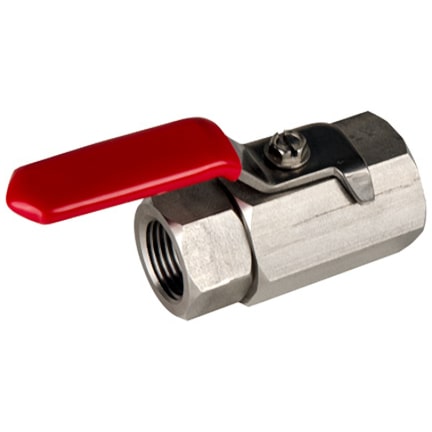
#1: If you need a two-port ball valve, does it need to control flow in both directions?
Flow Paths and Ball Valve Ports
One-way or unidirectional vs. two-way ball valves
The most common miniature ball valve is the two-port ball valve with two ports or connections. The option of choosing between a one-way or two-way ball valve sometimes shows up with metal ball valves designed to handle relatively high pressures, usually about 200 psi and higher. The difference between a one-way and a two-way ball valve is that flow direction matters.
One-way ball valves have a flow direction. This orientation is because one-way ball valve designs only seal and handle pressure flowing in one direction. A one-way valve ball has only one seat for sealing against the ball. Besides providing the sealing surface, valve seats also provide a surface that uniformly distributes force pressing against the ball.
Not only do one-way ball valves not seal against upstream pressure, but they also do not hold up well to the wear caused by this upstream pressure. Despite these limitations, unidirectional ball valves are a practical option because of their lower cost.
Two-way ball valves can adequately handle the pressurized flow from either port without leaking or premature wear to the valve components.
Three-way diverter (L-port) vs. mixing (T-port) ball valves
Miniature three-way ball valves usually come as one of two types based on the design of the balls inside the valve: L-port and T-port. The two ball port types also come in either an upright (vertical) or horizontal orientation.
L-port three-way ball valves (vertical and horizontal) have “L” shaped holes bored through the valve balls. T-port three-way ball valves have a “T” shaped passage running through the ball. L-port valves, sometimes called diverter valves, divert flow between different destinations.
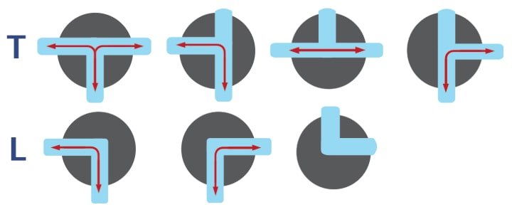
T-port and L-port horizontal ball valve flow patterns schematic.
L-port ball valves may or may not have an “off” or closed position depending on whether the valve body includes stops that limit the rotation of the handle. Horizontal T-port valves do not have an “off” or closed position. Vertical or upright T-port three-way valves do have an off or closed position.
Get a more detailed look at three-way ball valve flow patterns >>
#2: Multi-port ball valves offer the most customization options.
Four-way and five-way ball valves
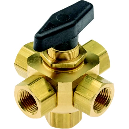
Ball valves also come in four-way and five-way designs with either four or five possible flow connections. The most common ball porting for these multi-port valves makes them suitable for diverting or mixing flow. There is usually an option for blocking one of the ports to add shutoff positions.
Four-way ball valves have more complex valve ball porting than three-way valves. The most common four-way ball porting is based on a five-way ball valve with the common port plugged. This option leaves the valve with two separate right-angle flow paths in the same plane running through the ball. Manufacturers usually list them as X-port valves. Turning the handle of these four-way ball valves diverts two different flow paths coming into the valve flow simultaneously to two alternate destinations.
The simplest five-way ball valves are diverter valves with an “L” or 90-degree hole that allows flow between the bottom or common port and one side port, but none of the other side ports. Five-way ball valves can have one port plugged to add an off or closed flow position.
Because of the customization flexibility of five-way ball valve bodies, valve balls for four-way and five-way valves come with more ball flow patterns than just L, T or X.
Four-way and five-way ball valves can be customized for various mixing options. Flow pattern options include:
- X-port flow
- L-port flow
- TT-port flow
- LL-port flow
- and more
Customized multi-port valve ball porting applications:
- Mixing
- Exhaust
- Diverting
- Selecting
Ball valve types and designs takeaways:
- Know whether you need a flow cutoff position
- Know the number of open valve ports the application requires
- Know whether the valve is for mixing, diverting or some other purpose
- Miniature ball valve types and porting have a lot of variations, so always ask about options
#3: For maximum flow, use a full port ball valve.
Ball Valve Design and Flow Efficiency
What is flow efficiency?
Flow efficiency measures how little or how much flow resistance there is as a fluid or gas passes through a valve, fitting or piping.
Right-angle ball valves create some flow turbulence and thus more resistance to flow than straight valves. Straight ball valves also have a relatively lower pressure drop across the valve than other types of valves. Full port or full flow ball valve designs provide even greater flow efficiency.
Full port ball valves have valve balls with holes ported through them with the same inner diameter as the pipe or tubing connected to the valve. Standard port ball valves use balls with smaller diameter ports than the flow coming into and leaving the valve. This constricted flow decreases flow efficiency and creates a higher pressure drop across the valves.
Full port versus standard port ball valves:
- Full port valves are physically larger
- Full port ball valves are more expensive
- Full port ball valves are more efficient and have higher flow rates than standard port ball valves
Find out more about Full Port Ball Valves vs. Standard Port ball valves >>
Flow efficiency takeaways:
- Ball valves by design have good flow efficiency
- Full port ball valves have the highest ball valve flow efficiency
#4: End connection options provide design flexibility and easier installation.
Miniature ball valves come in many connection types. These connection options provide easy installation and replacement:
- Hose barb
- Pipe thread
- Compression
- Push-in or push-to-connect
Hose barb, barbed or barbed insert connections
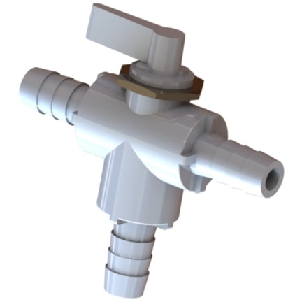
Valves with one or more hose barb connections are popular because they are considered tool-free and are quick to install. Hose barbs are designed for use with flexible plastic tubing.
Hose barb connection takeaways
Hose barb connections are known for being particularly leak resistant. Be aware that trouble-free connections require:
- Matching the hose barb design with the recommended tubing durometer
- Matching the tubing inner diameter to the hose barb size for the application
Find out more about the design and function of hose barb connections >>
Find out more about flexible tubing durometer and why it matters >>
Pipe thread connections
Fluid and gas handling valves and fittings commonly use threaded pipe connections because they are solid and leak-tight when properly installed. Most miniature ball valves available in North America come with NPT pipe thread. NPT (American National Standard Taper Pipe Thread) are tapered pipe threads and rely on a combination of thread sealant and a thread design that creates an interference fit to help make a tighter, stronger connection.
Threaded connection takeaways:
- Pair the same pipe thread type to ensure tight, leak-free connections
- Tapered pipe threads require properly applied thread sealants for leak-free connections
- Straight pipe threads require the use of a gasket, rubber washer, O-ring or sealing washer to create a tight seal
- Dissimilar materials increase the chance of overtightening and damaging or splitting female threaded ends
Compression connections
Compression connections connect rigid and semi-rigid plastic or thin-walled metal tubing to fittings such as valves or tubing unions. This type of connection is useful because it can effectively connect two tubing sections not made of the same material. It can also connect a tubing made of a different material than the fitting. As a bonus, it creates no flow restriction.
Compression fittings have an outer compression nut with a tapered seat, a barrel-shaped compression ring (ferrule) with tapered ends and a tapered seat on the receiving end of the fitting.
Properly tightening the compression nut presses the ferrule ends evenly into the seats inside of the compression nut and the fitting. Additional tightening deforms the ferrule, compresses it around the tubing, fills the space between the tubing, nut, and receiving end of the connection and seals the connection. Generally, do not reuse ferrules because they deform during the installation process.
Compression connections require proper installation for leak-free seals. Overtightening can cause leaks. A good rule of thumb for assembling compression connections is:
- Cut the tubing squarely and evenly and debur the end
- Slip the nut and then the ferrule over the tubing end
- Insert the tubing into the fitting until it bottoms out
- Hand tighten the compression nut until it is snug
- Tighten the nut about one-half turn more using a wrench
- Allow flow and see if there is any weeping from the connection
- If there is weeping, gradually tighten the connection until the weeping stops
Always follow manufacturers’ durometer specifications when using plastic tubing with compression connections. Plastic tubing walls must be stiff enough (higher durometer) to not collapse or move away from the ferrule when compressed. If softer tubing (lower durometer), use a tubing insert to reinforce the tubing wall.
Tubing minimum acceptable wall thickness is also necessary for metal tubing and rigid plastic tubing. With softer plastic tubing, the tubing inner diameter should match the tubing insert.
Compression connection takeaways:
- Careful installation of compression connections ensures leak-free seals
- Know the manufacturer requirements for tubing inner diameter and wall thickness
- Follow manufacturer durometer recommendations when using rigid or semi-rigid plastic tubing
Push-to-connect or push-in connections
Push-in or push-to-connect connections are a type for connecting metal or rigid and semi-rigid plastic tubing to unions and fittings such as ball valves without the use of tools, soldering or adhesives.
The working parts of push-in connectors are:
- An elastomer O-ring for sealing the connection
- A metal ring with gripping teeth that hold the tubing in place
- A tubing stop that indicates the tubing has been pushed far enough into the connection
- A release ring for disengaging the gripper teeth, releasing the tubing to remove it from the connection
Installation requirements for leak-free, reliable push-in connections:
- Plastic tubing must meet manufacturer durometer requirements
- Cut tubing ends squarely and evenly
- Properly debur the tubing ends
- Insert the tubing end into the fitting until it bottoms out at the tubing stop
- The outer tubing surface inside the fitting connection must be smooth with no scarring for the O-ring to seal properly
Push-in connection takeaways:
- Leak-free connections that will not pull apart require proper installation
- Follow manufacturer durometer recommendations when using rigid or semi-rigid plastic tubing
- Refresh tubing ends by cutting off scarred sections before being reusing the tubing and reinstalling the connection
#5: Materials matter because of chemical compatibility and food and potable water contact
Ball Valve Materials
Even though ball valves have a simple design, they all contain internal components. These components may be of different materials than the valve body. Material differences affect the valve’s compatibility with various chemicals, chemical mixtures and gases passing through it.
Be aware of which valve components will contact the fluids passing through the valve. These are sometimes called wetted parts.
Typical ball valve components:
- Body
- Stem
- Seals
- Seats
- Handle
- Packing
Ball valve materials for potable water or food contact
Materials that come into contact with foods and potable liquids are subject to regulatory control.
Manufacturers of commercial food equipment and food processing equipment used in the United States are responsible for using materials that comply with FDA regulations. Rules cover both raw materials and the appropriate end-use or real-world application of components made from these materials. Appropriate end-use rules consider factors such as exposure time, temperature, and acidity.
The NSF sets standards for materials that come into contact with drinkable water in the United States. They base these standards on testing for substances that can leach into drinking water from a valve's interior or wetted surfaces.
US materials and components standards for foods and potable water:
- FDA Code of Federal Regulations Title 21 parts 170 through 199
- NSF/ANSI/CAN Standard 61 Drinking Water System Components
- NSF/ANSI Standard 51 Plastic Material and Components Used in Food Equipment
When using valves for food and potable water applications, be sure the manufacturer clearly states that they make their valve from compliant materials or materials approved for food or potable water contact.
A particular application may require an NSF certified valve. If so, the manufacturer may provide this NSF certification information, so ask. NSF approved food contact materials are also FDA compliant.
Find out more about materials that are safe for direct food contact >>
An example of the effect of different ball valve component materials
Ball valves often use soft seat designs where an elastomer or plastic is the seat material. Using these softer materials provides a better seal that is more resilient, lighter and less expensive than a hard metal seat. Because of that polymer seat, a metal ball valve with a polymer seat will have an upper working temperature limit.
Ball valve materials takeaways:
- Plastics tend to be more corrosion resistant than metals
- Metal valves tend to have higher burst pressures than plastics
- Metal valves tend to have higher operating temperatures than plastics
- Food processing, contact and potable water applications have special material requirements that may include NSF certification
#6: Understand the maximum temperature and pressure requirements.
Technical Specifications
CWP, Cold Working Pressure
CWP is the maximum working pressure a valve can handle at temperatures between -20°F to 100°F (about -29°C to 38°C).
Operating temperature range
A valve used within its operating or material temperature range will not suffer damage or failure to any of its components or have a shortened working life.
Maximum operating pressure and temperature
The maximum safe operating pressure or PSI rating of a valve is provided based on its maximum safe operating temperature.
Blow out proof stems
Miniature ball valves with blow-out proof stems have mechanical design elements that prevent high-pressure surges from blowing the valve stem out of the valve body.
Cv (flow coefficient) and flow efficiency
Cv stands for flow coefficient. It represents how efficiently a gas or liquid can flow through piping, a fitting or a valve. Many manufacturers provide ball valve specifications, including their flow coefficient. If the Cv number of two valves is known, a higher Cv number means a valve provides a higher flow under the same operating conditions.
#7: Use only ball valves designed and certified for applications involving steam and combustible gases.
Dedicated ball valve types
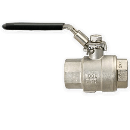
WOG, Water, Oil or Gas
WOG is an older term that is no longer widely used. In general, it simply indicates that a ball valve is suitable for general use and can handle water, oil or gas but not steam or combustible gases. Ball valves for use with combustible gases have specialized additional design elements and certifications that approve the valves for this use.
WSP, Working Steam Pressure
WSP is the maximum steam pressure a ball valve can handle. Generally, no miniature ball valve will be suitable for use with steam unless the manufacturer clearly says it is and provides the Working Steam Pressure. SWP, Steam Working Pressure has the same meaning.
Technical specifications takeaways:
- Know the critical ball valve technical specifications needed
- If appropriate, look for third-party testing and quality assurance certification
- Don't hesitate to ask us questions if a required specification is missing or not clearly explained
Ball Valve Selection Final Thoughts
Ball valves are simple, sturdy shutoff valves that can be closed with a quick quarter-turn of the valve handle. They are reliable and work even after long periods of idleness. In contrast to industrial ball valves, miniature ball valves come with a broader range of material and design options. Look for and ask about our miniature ball valve options to find the best choice for an application.
Take Advantage of Our Expertise
We offer a line of ideas, so if you don't see it - ask for it. Let us turn your ideas for pneumatic or fluidic circuitry assemblies into reality — from conception to finished product.
« Go back to the blog homepage